RS Blog 21 - Plumbing, Electrons and Speed Sensors
Doing things to make this beast a few steps closer to life. Always pushing myself to learn new things and use new methods instead of relying on existing skills or others. In today’s update we explore a little CAD and Hall effect sensors.
Wheel Speed

Since I’ve gone off the map on engine management and power distribution systems, more details on setup in a future post…, I figured I’d take a small step further and monitor wheel speed on all for corners to open up options for learning vehicle dyanmics and traction control.
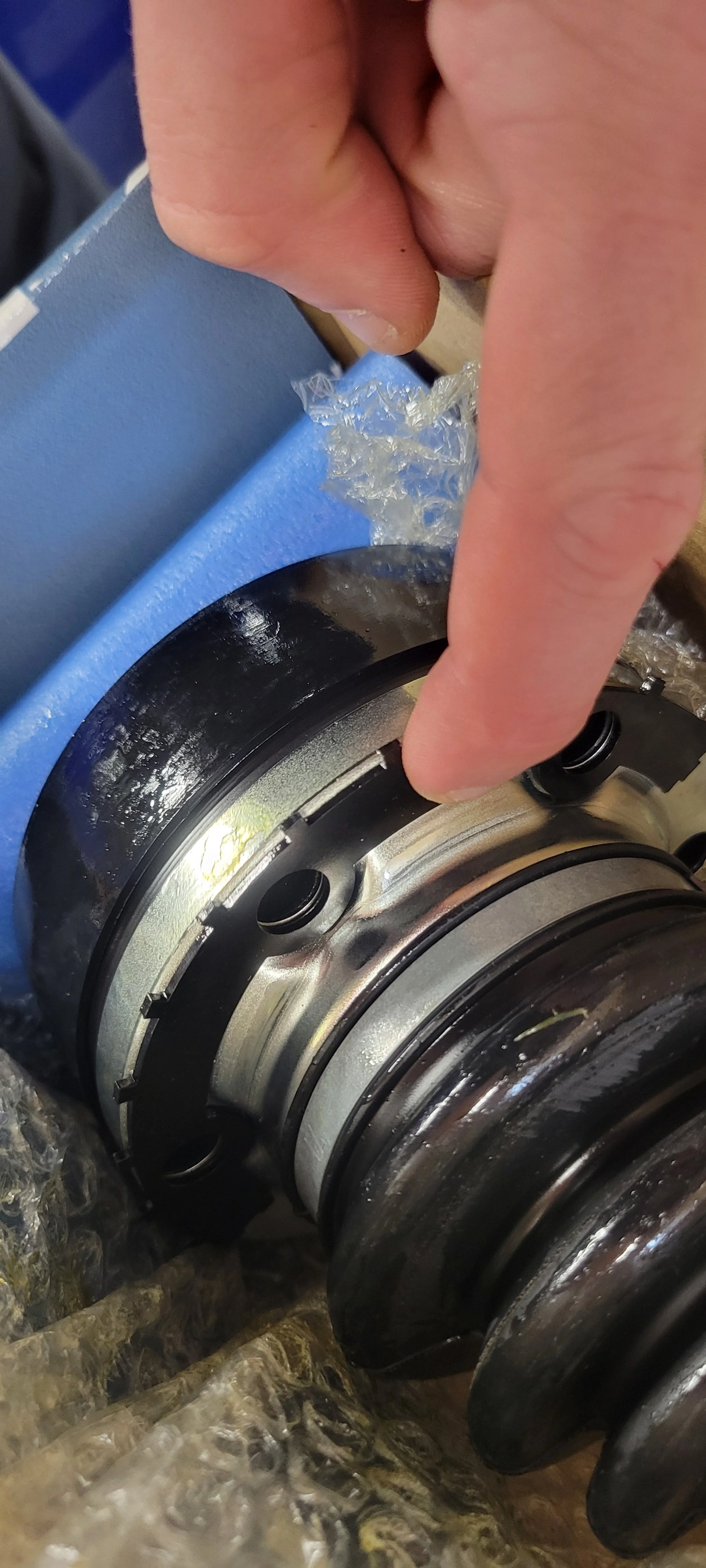
Ultima doesn’t list any options for wheel speed sensors, I think there is a factory option for monitoring transaxle output shaft speed on one side. I’ve learned about how awesome is Send-Cut-Send. A bit of pondering, math and CAD time and voila figured out a pair of 24 tooth trigger wheels for the front hubs and rear axles. the front design was covered in blog 18, now we are looking at the rears.
Decided to mirror some designs I found online with slight tweaks. Others I found relied on only 6 teeth, minimal sensitivity at lower speeds. Or they stacked between the half shaft and gear box, moving the axles out a tiny bit. To minimize any binding or issues from spacing the axles out I’ve opted for a two piece configuration that interlocks and acts as the washer for all 6 axle bolts.
Rear sensors are also 24 tooth to make front and rears closer aside from wheel/tire diameter offset will throw things off. At least in settings they should be near each others in terms of pulses per revolution.
Send-Cut-Send is the best, they even included a treat with this part delivery.
Minor Mounting Updates

First up is the best, most race car part of the build. Aside from ya know the entire car… Intercomm system for tunes and telling your passenger everything will be fine while hurdling into the apex way faster than you wanted.
After much deliberation I found the home above pedals, shouldn’t be in the way of anything and is possible to remove with a few bolts. The bracket will be riveted in place while the intercomm box mount has added rivetnuts. Minor benefit, maybe, my feet can no longer kick random stuff above pedals. In the picture you’ll notice the battery cable for my PDM, routing inside the fiberglass shell for a clean view up front. Piece of trivia I’ve learned over a decade of playing with race cars… clean wire and hose routing makes maintenance 1000% easier. Simpler to clean, simpler to find issues and less issues crop up.
Getting the HVAC lines from front to back
Another relatively simple task I could check off the list was heating and cooling of the cockpit, simple pairs of lines to the engine bay from underdash mounted HVAC. Only minor challenge was through each side pod. Manual recommends cutting a portion of top inner edges from each pod then filling back in using sealant and foam. I’d rather have the ability to replace lines in the future with less headache and opted to drill holes and add grommets. Not sure how helpful it will be considering I really won’t be able to access the HVAC side with center section mounted, but this leaves me hope….maybe.
I also installed rivetnuts and stainless loop clamps to secure the lines inside each pod. May add a cover later that utilizes the same mount points, but that is for another day. Thus far I haven’t drilled myself into a corner, all parts are still removable with the clecos.


Power Connections
Have to make those pretty crimps for the PD16 and Nexus R5. The Amphenol connectors are so nice to work with, definitely enjoyed making the pair of cables.
Both have dedicated power connections to the battery. Grounds are through the chassis to utilize the disconnection switch bolted ground to chassis
This is enough for this post. Definitely an entire blog will be dedicated to the chassis and engine wiring. Soon!