RS Blog 18 - Sensors, Fitments and ECU Mounting
Another set of progress on the build. Everything seems to require a bit of time, thought and grinding to get a perfect permanent home. Today’s blog will cover the custom wheel speed trigger rings, part of HVAC installation, trimming center console and finally picking a home for the Nexus R5. All big milestones as the pave the way forward for many more steps.
HVAC Mounting
Nothing terribly special here, but wanted to capture my progress on this item. Ended up massaging the placement until it was very square and close to steering column.

Wheel Speed Rings


I’m working on a rear wheel speed trigger ring that should pull from the axle. More to come, but send cut sent is going to be helpful.
Ultima Lift Controller
Sorry not Sorry….
The controller module has such limited control functionality that I had to understand what is going on inside. The box just seems to pass through the button from lowering suspension and it only opens the solenoid on lift kit. The raise control powers up the pump and opens solenoid, however without them connected it just triggers a buzzer. With a bit of bench testing I found the very limited function. I hoped each button would light up based on current raise/lower status, but nope.
Additionally the wiring indicates 40A required, plus another 10A for the control box. While the pump itself is labeled as 250W max (~20A). Something ain’t adding up. Pulling out my reverse engineering degree.
The very fancy lift kit controller is comprised of two 555 timers, two relays and a buzzer with a few resistors and capacitors to bias the 555 timers. Yes 555 timers are the most basic IC ever and the entire box is not potted. Nothing about it is ready for automotive usage let alone a super car…. I’m really disappointed in the box, not only does it hide a pair of relays that are controlled externally by another relay, but nothing is secured and its using super basic circuits.
I am replacing all of this non-sense with digital controls via the Nexus R5.
On a positive note, the machining of the hydraulic lift and packaging for physical arrangement is great. That part I could have never figured out and I am still very happy I purchased the setup. As an electrical engineer I’m just a little disappointed, but will fix it.

Center Console and Parking Brake
This part installation is more simple and straightforward. I’m sure someone could point out the gaps in each panel, but I’m comfortable with the result. Use a Dremel with metal cutting bit and patience to trip it down. After trimming down the fiberglass/carbon console I found the parking brake to interfere with the console when fully released. Simple problem requires a simple solution..
Drilled a small hole for a 10-24 screw at the appropriate stop point, then cut a small portion of vacuum hose and bolt it together. Now has a really solid feel and I cannot accidentally hit the console.


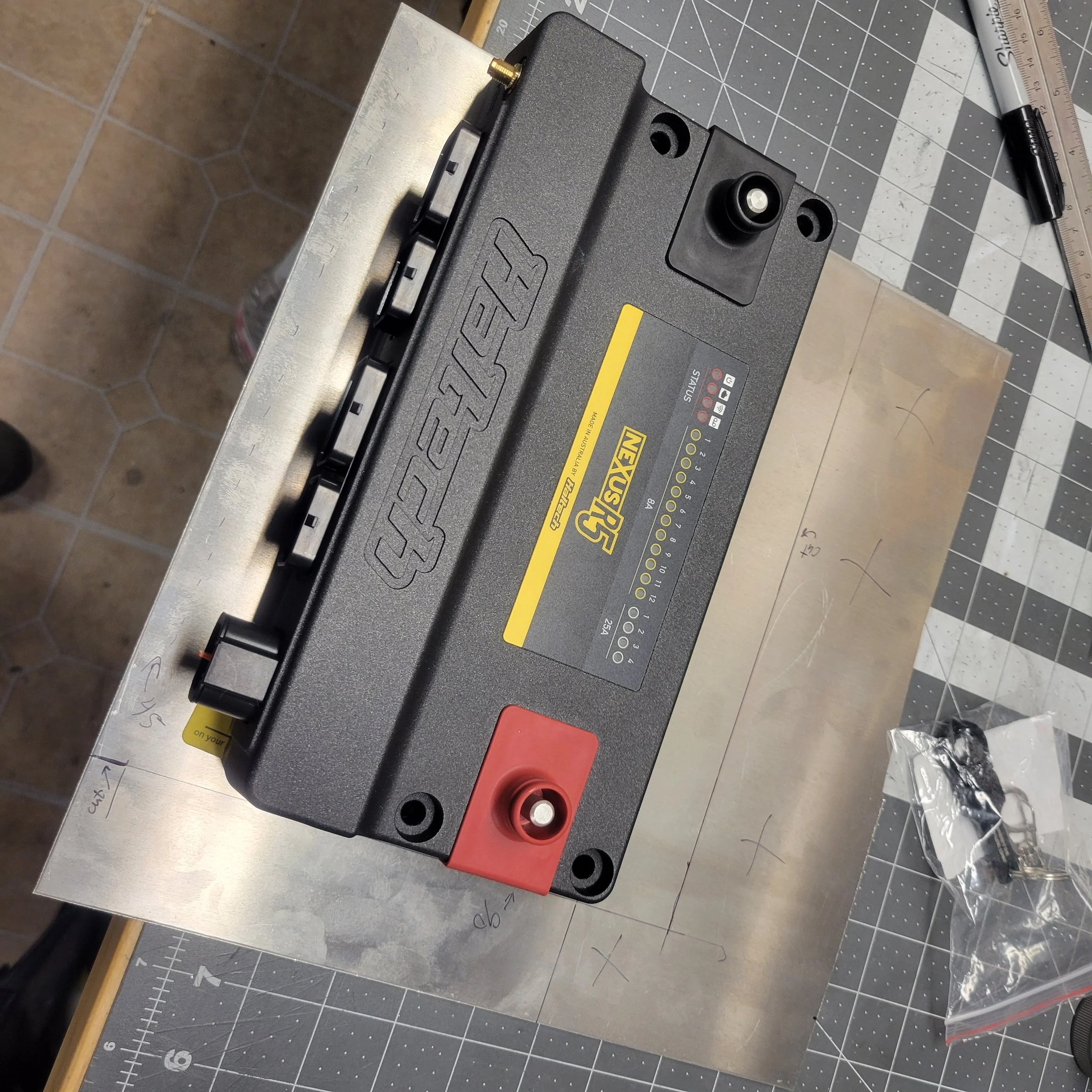
ECU home
My biggest headache is the pesky most important part of this build. The brain of it all, Nexus R5. Many hours were spent staring at the chassis and holding it in various spots. I considered near the front of tub below windscreen, it doesn’t have enough space because of windscreen wiper. Looked at the top right side under dash, but HVAC tubing and vents interfere too much. The factory places them within the passenger side pod and I tried my best to avoid it as pod storage is so crucial when the car has no space. Some folks put them into the spot behind the wheel well as it is dry, but this doesn’t allow easy access. Engine bay spots are not really an option because of heating or just limited space back there. I finally decided on top of passenger side pod with a bracket to protect. Overall I wish somewhere else would have worked, but nothing seemed reasonable.
Key features of my solution:
Panel provides water resistance from splash/leaks above
Wires looping down then back up through side pod eliminates opportunity for water tracking into plugs
Gap on outside edge for wiring into dash area
Gap on inside for AC line routing
Removable via rivet nuts
Uses top space that is likely not as useful and stuff shouldn’t hit the ECU